By Pete Apple
Feeder mechanism damage remains one of the more challenging areas of modern mint-error attribution. Researchers must work with incomplete documentation about coining presses and feeder systems. In addition, mints often use multiple presses and feeder types at the same time.
As a result, clear identification of feeder-related die damage can be difficult. However, careful analysis of damage patterns can still reveal the most likely mechanical cause.
This article examines die damage patterns in feeder mechanisms observed from 1945 through approximately 1990. The examples represent the mechanisms most likely responsible for specific types of die damage.
Understanding Feeder Mechanisms in Coining Presses
Feeder mechanisms perform a critical role inside a coining press. They transport, align, and position planchets into the striking chamber. Once the dies strike the coin, the system ejects the finished piece and prepares the press for the next planchet.
Modern presses operate at very high speeds. Consequently, mechanical wear, timing errors, or misaligned components sometimes occur. When these failures develop, feeder components may strike or scrape the coin dies.
This contact produces distinctive die damage patterns that later appear on struck coins.
This study [1] forms part of a broader research project examining coin presses, feeder systems, and their associated die damage patterns. The goal involves identifying mechanical causes based on the appearance of damage seen on coins.
To simplify identification, the research divides feeder-related die damage into eight primary patterns observed since the early 1900s. This article introduces two of those patterns. Future installments will examine the remaining types.
PATTERN 1945 to 1966: VARIOUSLY ORIENTED DIE SCRAPES NEAR RIM
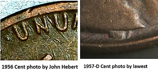
Examples of feeder mechanism damage during this period remain relatively uncommon. When they appear, they usually share several characteristics:
- Scrape directions range from horizontal to angular (around ±45°) and occasionally vertical
- Damage typically extends 2–3 millimeters inward from the rim
- Scratches or scrapes appear light but clearly directional
Although rare, these features can help attribute a coin to a specific feeder mechanism design.
The 1945 Conversion Unit for Coining Presses
In 1945, machinist William P. Kruse of the San Francisco Mint designed a conversion unit for coining presses. [2] He collaborated with Joseph Steel, the Superintendent of Coining at the San Francisco Mint. Their design introduced a Dual Coining Press conversion system.

The United States later issued the patent in 1949 (U.S. Patent 2,470,102).[3] The design allowed existing presses to convert quickly into dual-operation systems.
Widespread Adoption of the Conversion Unit
The conversion unit likely saw wide installation across several press types, including:
Bliss coining presses
Ferracute presses still in production at the time
Mint records from 1945 reported that the device already operated on domestic and foreign coins the size of quarters or smaller. Because operators could easily attach the device to existing presses, the design spread quickly through production facilities.[4]
Interestingly, examples of feeder mechanism die damage remain scarce during the decade following its introduction. Nevertheless, when damage from this era appears, this conversion unit likely produced it.
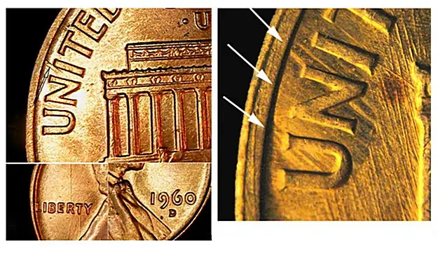
Pattern: 1966 to ≈1990 – Horizontal and 30° Angular Die Scrapes
Beginning in the mid-1960s, another feeder mechanism began producing identifiable die damage patterns.
These patterns display:
- Horizontal die scratches, or
- Angular scrapes oriented around 30° (±10°)
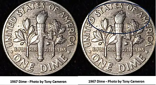
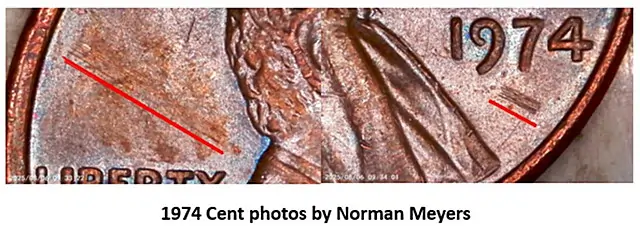
Because surviving examples remain limited, researchers cannot yet define a complete set of characteristics. However, two documented coins illustrate the pattern clearly:
- 1967 Roosevelt dime with light horizontal die scratches
- 1974 Lincoln cent showing tightly compressed scratches at an angle
The Dual Coin Press Slide Finger Mechanism
These scratches most likely result from the sliding motion of a slide finger feeder mechanism used in dual coin presses.
Inventors Derald Henry Kraft and Ronald Herman David Armbruster filed the patent for this system in 1963. The United States Patent Office granted the patent in 1966 and assigned it to the E. W. Bliss Company.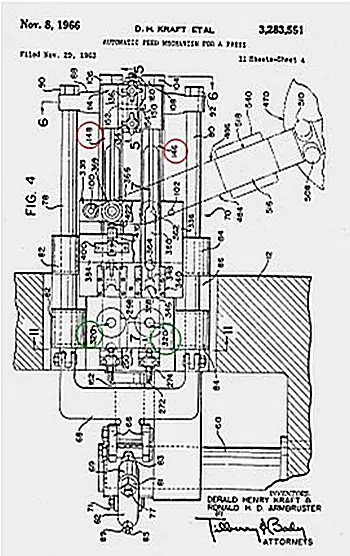
The patent describes the feeder action as a reciprocating slide finger mechanism that moves across the press to deliver planchets.
In simplified terms, the mechanism works as follows:
- A slide finger moves along a path perpendicular to the dies.
- The mechanism connects to the press drive system.
- The slide finger moves between retracted and extended positions.
- In the retracted position, it receives a planchet.
- In the extended position, it delivers the planchet to the lower die.
This sliding action occasionally contacted the die surface. When that occurred, it produced the horizontal or ~30° scrape marks seen on coins struck during this period.
Why Identifying Feeder Damage Matters
Feeder mechanism damage offers valuable insight into minting technology and mechanical failures. When numismatists identify these patterns correctly, they can:
- Distinguish die damage from post-mint damage
- Understand mint production methods
- Attribute errors to specific press and feeder designs
Because feeder-related damage remains rare, each documented example contributes important data to the ongoing study of minting technology.
Future articles in this series will introduce additional feeder mechanism damage patterns and further refine identification methods.
More Articles on Feader Mechanisims from Pete Apple
- Feeder Mechanisms and Die Damage Patterns (1896–1945)
- Feeder Mechanisms and Die Damage Patterns (1945–1990)
- Feeder Mechanism Die Damage Patterns (1990–2018)
- Feeder Mechanism Die Damage Patterns (2018 – Present)
References
[1] Apple, Pete. A Study of Feeder Mechanism Die Damage Patterns.
[2] Annual Report of the Director of the United States Mint (1945). Treasury Department of the United States.
[3] Conversion Unit for Coining Presses, U.S. Patent 2,470,102. Inventors: William Peter Kruse and Joseph Wynn Steel.
[4] Automatic Feed Mechanism for a Press, U.S. Patent 3,283,551. Filed November 29, 1963. Assigned to E. W. Bliss Company.

: A Diagnostic Guide for Collectors")