By Pete Apple
Understanding feeder-mechanism die damage patterns from the late 19th through the mid-20th centuries is complicated by two key factors: incomplete technical documentation and the contemporaneous use of multiple press and feeder designs.
As a result, the examples presented here should be considered representative of the most likely mechanism responsible for a specific die damage pattern, not definitive attributions in every case.
Feeder mechanisms are designed to transport, align, and position coin planchets into the striking chamber of a coining press with precision. After striking, the coin is ejected, and the process repeats. High-speed press operation, combined with wear, timing errors, misalignment, and mechanical failures, can cause feeder components to contact the dies. When this occurs, distinct and repeatable die damage patterns may result.
This article is part of a broader exploratory study of coin presses, feeder mechanisms, and the die damage patterns most likely produced by each system.[1] The goal is to provide collectors and researchers with a streamlined framework for identifying probable feeder mechanisms based on observable die damage.
Since the early 1900s, eight primary feeder mechanism die damage patterns can be identified. Two are discussed here; others will be presented in future issues.
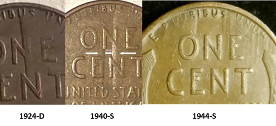
Pattern 1896–1945A: Vertically Oriented Die Dents
Vertically oriented die dents from this period typically display:
- Straight edges
- Smooth surfaces
- Uniform widths (though widths may vary between dents)
These characteristics suggest die dents, not die scrapes. Scrapes generally exhibit ragged edges and irregular widths.
Possible Feeder Mechanisms in Use
During this era, up to three feeder mechanism styles may have been in simultaneous operation:
A pusher feeder used on a E.W. Bliss Company press[2]
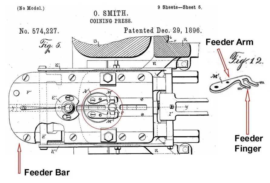
The 1896 patent feeder mechanism by Oberlin Smith[3]
Smith’s revised 1909 patent mechanism [4]
In Smith’s 1896 patent design, the feeder bar includes finger arms terminating in downward-bent, two-pronged feeder fingers. These fingers are relatively small, no larger than approximately 3 inches, and the inner length of each finger is no more than about half the diameter of the die over which it passes while delivering the planchet.
This physical limitation aligns with observed damage patterns that extend over no more than approximately half the coin’s diameter. Such correspondence strongly suggests that these marks are die dents caused by a feeder finger striking into the die surface rather than dragging across it.
The geometry of the feeder finger and its range of motion provide a logical mechanical explanation for the observed dent characteristics.
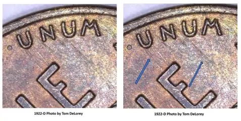
Pattern 1896–1945B: Vertically Oriented Die Scrapes
A second pattern observed from the 1920s through the 1940s consists of vertically oriented die scrapes. These are characterized by:
- Ragged edges
- Irregular widths
- Linear scraping appearance
Unlike the previous pattern, these features are consistent with die scrapes, not dents.
Case Study: 1922-D Lincoln Cent
One example occurs on a 1922-D Lincoln cent struck at the United States Mint (Denver facility).
During this period, three feeder styles may have been in operation:
- A Bliss Press pusher feeder [2]
- A Ferracute press mechanism styled after Smith’s 1896 patent [3]
- A revised feeder mechanism styled after Smith’s 1909 patent [4]
The Bliss press had been in use since 1902 and was described as having an accurate and reliable feeding mechanism. [5]
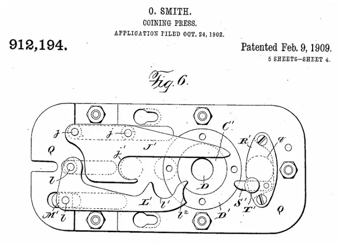
However, the most probable cause of the 1922-D die scrape pattern may be the gripper (L₁) described in Smith’s 1909 patent. In that design, loosening at the feeder arm connection point (l) could allow misalignment of the gripper point (l₂). Such misalignment increases the likelihood of the component scraping across the die face.
From a mechanical standpoint, this explanation is more plausible than attempting to attribute the distinctive scrape pattern on the 1922-D cent to the other feeder mechanisms known to be in service at the time.
Why Feeder Mechanism Attribution Matters
Identifying feeder mechanism die damage patterns:
- Helps distinguish mechanical damage from other forms of die deterioration
- Provides insight into press technology in use at specific time periods
- Assists specialists studying mint production practices
- Contributes to more accurate die state analysis
Because multiple press types were frequently in concurrent use, attribution remains probabilistic. Nonetheless, repeatable damage characteristics allow for increasingly confident identification when mechanical design and observed die geometry align.
Future installments will examine additional feeder mechanism damage patterns from the early 20th century onward.
More Articles on Feader Mechanisims from Pete Apple
- Feeder Mechanisms and Die Damage Patterns (1896–1945)
- Feeder Mechanisms and Die Damage Patterns (1945–1990)
- Feeder Mechanism Die Damage Patterns (1990–2018)
- Feeder Mechanism Die Damage Patterns (2018 – Present)
CITATIONS
[1] A STUDY OF FEEDER MECHANISM DIE DAMAGE PATTERNS by Pete Apple,
[2] Bliss, EW Co., Presses, Dies and Special Machinery BUILT BY E. W. BLISS CO., 1906, BOROUGH OF BROOKLYN, NEW YORK, U. S. A., AMERICAN BANK NOTE CO., NEW YORK, page 156. Annual Report of the Director of the Mint, Annual Report of the Director of the United States Mint, Published by the Treasury Department of the United States. Easily accessible at: https://nnp.wustl.edu/library/publisherdetail/51, 1902, page 135 (Description of feeding process. Although the Press type is not identified, Fig. 21 is a Bliss Press – see page 6 @ [1]). (Fig. 21 may be found in the set of Figures following page 136).
[3] UNITED STATES PATENT OFFICE. OBERLIN SMITH, OF BRIDGETON, NEW JERSEY. COINING- PRESS. SPECIFICATION forming part of Letters Patent No. 574,227, dated December 29, 1896. Application filed June 5, 1896, Serial No. 594,454, (No model.) A Ferracute Press was in use at the Mint at least as early as 1892: The United States Mint, Philadelphia. National Archives and Records Administration (NARA), Philadelphia, PA. Record group 104, entry 1, box 179, Letter from Ferracute Machine Company, Bridgeton, New Jersey, U.S.A., January 7, 1893 to Col. O.C. Bosbyshell, United States Mint, Phila., signed by Oberlin Smith.
[4] UNITED STATES PATENT OFFICE, OBERLIN SMITH, OF BRIDGETON, NEW JERSEY. CONING- PRESS. No. 912,194. Specification of letters Patent. Application filed October 24, 1902, Serial No. 128,654. Patented Feb. 9, 1909. Also see: Burdette, Roger W., from Mine to Mint, Senaca Mill Press, LLC, 2013, pages 57f, and 527ff. (Includes discussion of automatic feeder tube from 1910).
[5] Bliss, EW Co., Presses, Dies and Special Machinery BUILT BY E. W. BLISS CO., 1906, BOROUGH OF BROOKLYN, NEW YORK, U. S. A., AMERICAN BANK NOTE CO., NEW YORK, page 156.


Informative article as always!
Thank you. I found the research challenging and interesting!
You learn something new every day.
I have been amazed with an overload of new information, at times!
You can never wrong with a article such as this. Learned alot
I Appreciate your saying this!
Learned something new
Interesting, isn’t it? I, also, have learned!
Almost anything produced at speed will have flaws – good luck finding them!
I suspect you are correct! Finding the precise mechanism/part is sometimes (most of the time) quite elusive!
Good Stuff
Thanks for commenting! I appreciate your feedback!
Good information
Appreciate your saying this!
Great article with terrific insights on how errors are caused.
Thank you! I have been intrigued with all I have learned on this project!
Interesting information
Thanks for commenting!
Great article! Always like to hear more about coin production, not just the coins themselves.
Thank you! It has been an interesting project!
I continue to maintain records and a Census of Feeder Mechanism Damage Patterns!
Very informative and thanks for posting it.
You are welcome! Pleased that you found it helpful!
Nice to know about feeder mechanisms.
Thanks
Very interesting article
Thank you!
It’s always fascinating to me to learn more about the coining process! Great article!
Thanks so much!
really interesting. never had any idea it was that complicated,
It is probably a bit more complicated than appears. This is basically a summary of a summary!
I love learning the in’s and out’s of mechanical devices. Great article.
Thank you!
The different presses used at any one mint facility makes one look for different damage due to feeder fingers. Like recently trying to figure out was a die hubbed with the single squeeze method or the more traditional method.
Thanks for commenting!
Ken Potter reports: “According to a November 17 Coin World report, George Hunter, Mint assistant director of Process and Quality Control, confirmed that single hubbing presses
were used to make all the 1997 dies.”
I have not seen documentation that this applies to all following years or not. Confirmation that it does apply would be useful information.
@Pete Apple, as a “gadget girl” your research on finger feeders fed my curiosity, as to how and why, did coins get those symmetrical line marks on the fields, after discovering one. Prior to your articles, I had no knowledge of the terminology, let alone the equipment involved in the production of coins. Your articles are great reads which enhance my understanding of the mechanisms involved, leading to the results I see in hand. #CarryOn.
THANK YOU!
I appreciate your support and encouragement!